While I was playing with the previous trackball, I began to understand what I needed from the next one. Yes, the next one. We are going serious now. So the next model is "X-keys L-track". Originally, it was made by "CST" and it was a cult device. Now the rights have been bought by "P.I. Engineering" and they are continuing to produce them manually, piece by piece. So I decided to give it a try.
This trackball is a symmetrical, index-controlled, dynamic, 2.25" (~57mm) model.
As I said, I am not a big fan of thumb-controlled conception, so this one is also index-controlled.
The most significant difference and advantage here is the dynamic moving mechanism based on the rolling bearings. As a result, it requires much less maintenance because dust is not building up over dynamic points of contact. The annoying stiction effect is also not presented here because you do not need to overcome the force of friction every time to bring the ball out of its rest state. Some users point out that using bearings causes much more noise, but for me personally, it is not a problem at all, and overall, I like mechanical sound feedback.
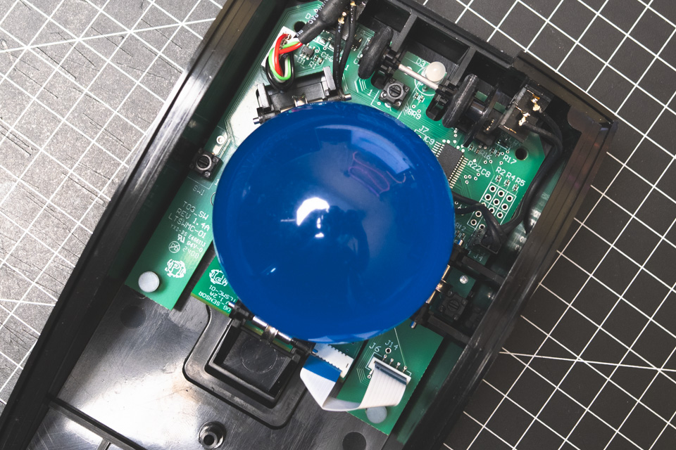
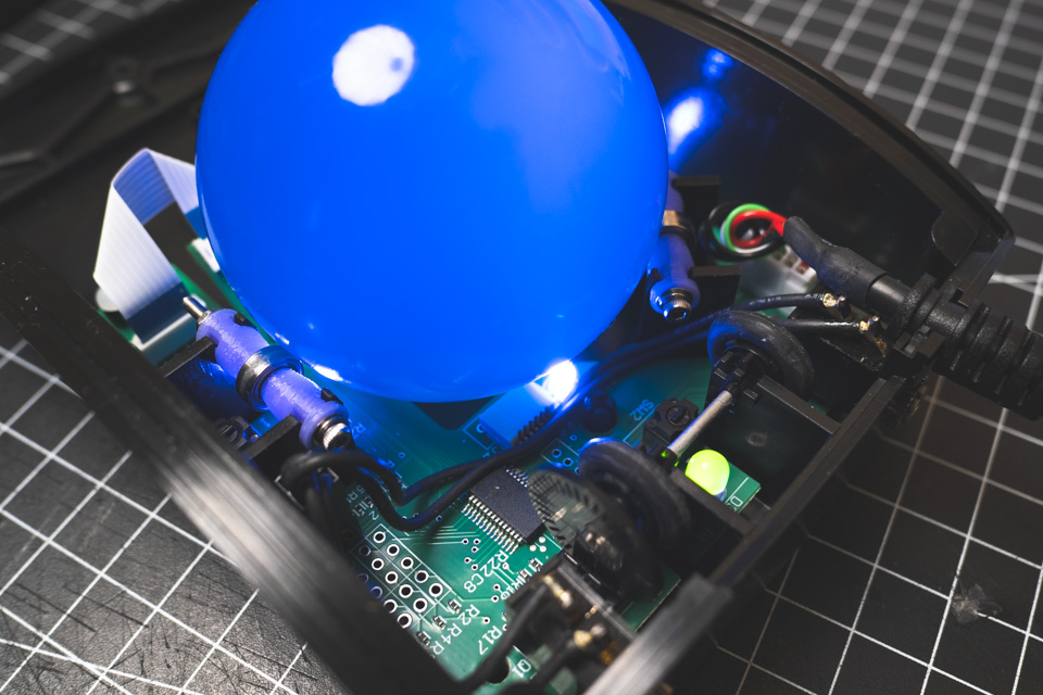
The ball itself is here on the biggest side and almost equal to 57mm pool ball, which some users are happy to use as an alternative.
The scroll wheel is in a bit of an unusual place for such devices, and I need to get used to it. It is stepless, by the way, and silky smooth... kind of.
Out of the box, it has three buttons for left, right, and middle mouse clicks.
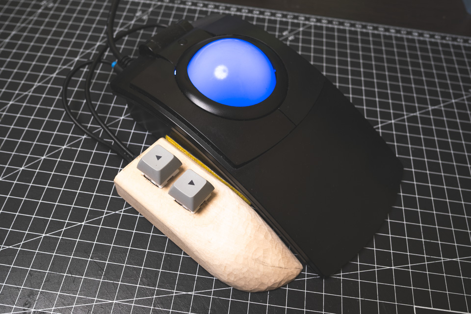
On the front side, you can find two 3.5mm jack ports, and they are not for audio. These ports are mono and have only two contacts to fit with any type of contact switch. You can literally just take a mono audio cord with a 3.5 jack on one side and solder two wires from the other side to the contact legs of any mechanical keyboard switch.
Sounds perfect, huh? But as I mentioned, it is a very, very old-fashioned device that is now manufactured by a small company. When I am checking the construction of this device with the day white LED light, I can definitely see that even the plastic of different parts can have different shade. Maybe they are from different batches or just refurbished from an old stockpile. But the other side of the old-fashioned coin is that this device is simple to customize. And this is what I am planning to do.
Real ball bearings mod
The first fairly significant modification will be in the rolling mechanism. Originally, it is based on special solid metal rollers that are inserted into adapters with their axial pins. Adapters are inserting into special slots in the case. The problem is that these are still just thin metal pins that rotate in plastic holes. Any dirt that gets wind up on them is felt very clearly and spoils the tactile sensations.
During the existence of this device, it has already undergone several changes, and one of them is a groove milled into the middle of the roller. As I understand the idea, it was for the sake of preventing dust from building up on the roller and getting between the roller and ball. And from my experience, I see that this groove brings up more issues than solving.
Firs, and the biggest one is that 3 tangent points of contact turn into 6 points of contact. Let me explain. In such designs, rollers have only one axis of rolling. So, for straight types of movements, the ball is spinning on the point of contact with the roller surface. For example, a horizontal roller during straight vertical ball movement or a vertical roller during straight horizontal ball movement. And when instead of a simple tangent point of contact, you have two pointy ones, it feels like a knife over scratches.
The second one is that because of the groove, the roller has less material in the middle, so contact points with the ball are higher and ball position is lower. So instead of lying on rollers, the ball is jamming between them.
So let's replace primitive rollers with full-fledged bearings and make their contact points with the ball a little lower so that the ball rolls on them more freely.
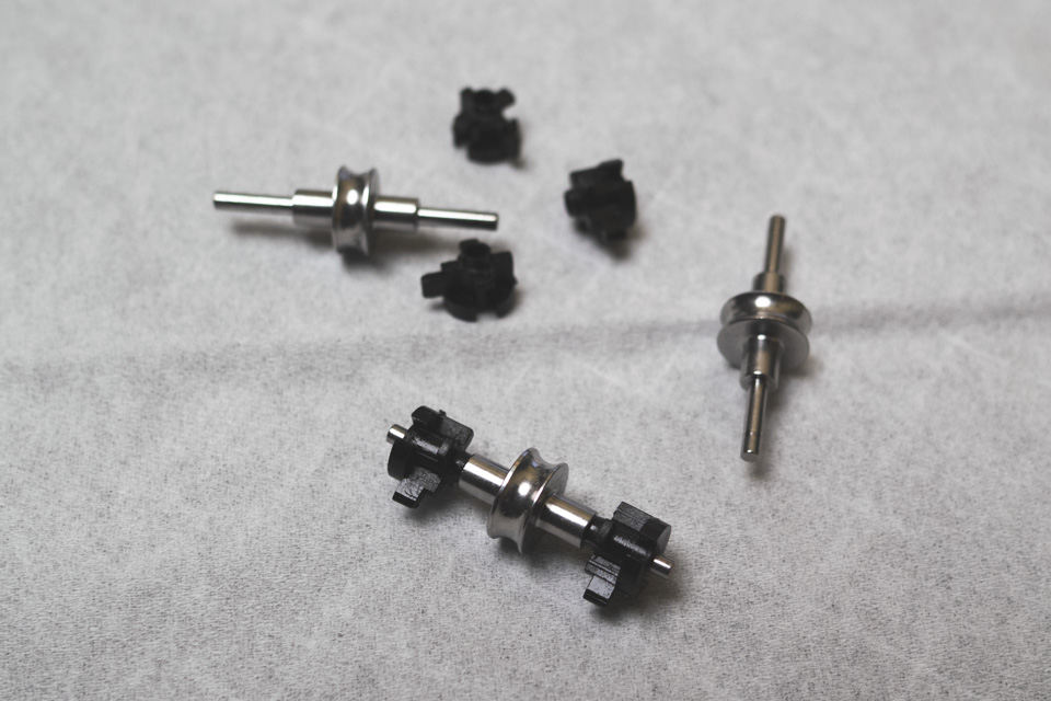
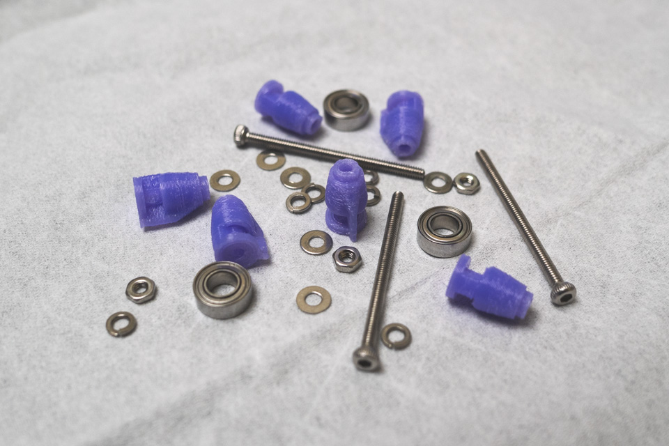
I analyzed the structure of the original rollers, adapters and case slots. Based on this I designed my CAD version of the preassembled rolling modules.
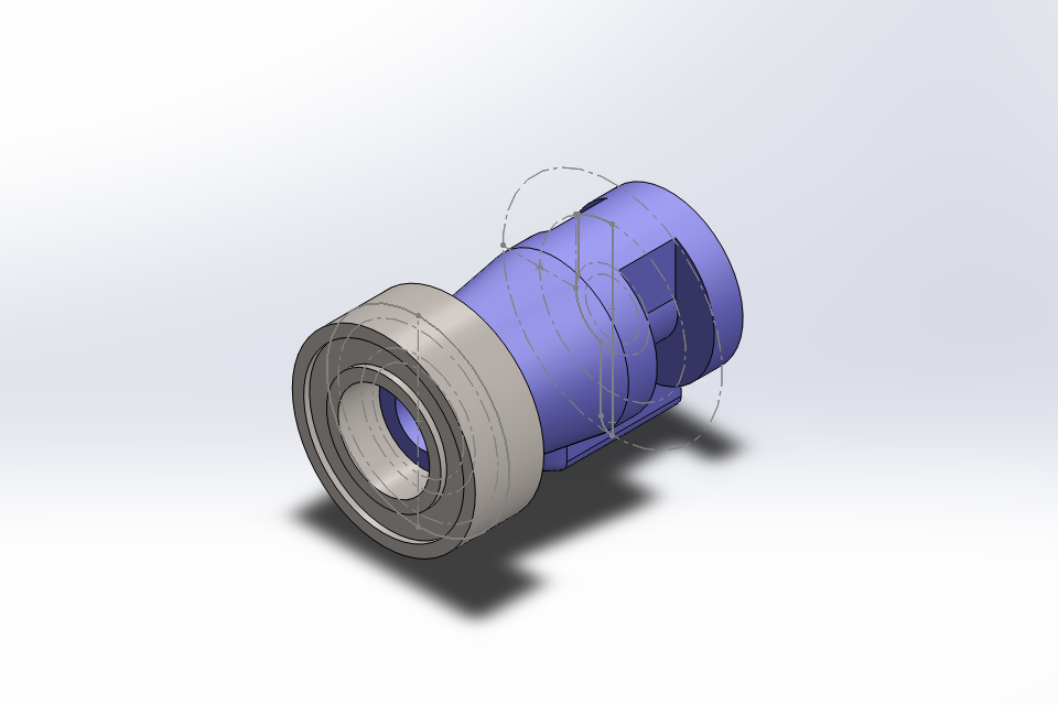
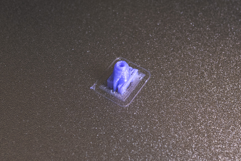
Adapters was printed on FDM printer with PETG. In the future I will think about SLA version with some "tought" resin. But for now it was a big push to finally figure out settings of my "temporary" FDM printer.
Here are all the details before assembling:
1) As rollers I got a set of hight quality miniature bearings with an outer diameter of 8mm, inner diameter of 4mm and a thickness of 3mm.
2) As an axel, I am using DIN912 M2 30mm bolts.
3) 6 printed adapters.
4) The bearing is clamped on the axle between the adadapters with DIN439 M2 nuts.
5) To tighten this sandwich and prevent it from getting loose, I am using DIN125 M2 washers and DIN127 M2 spring spacers.
And this is how the rolling module looks like when assembled.
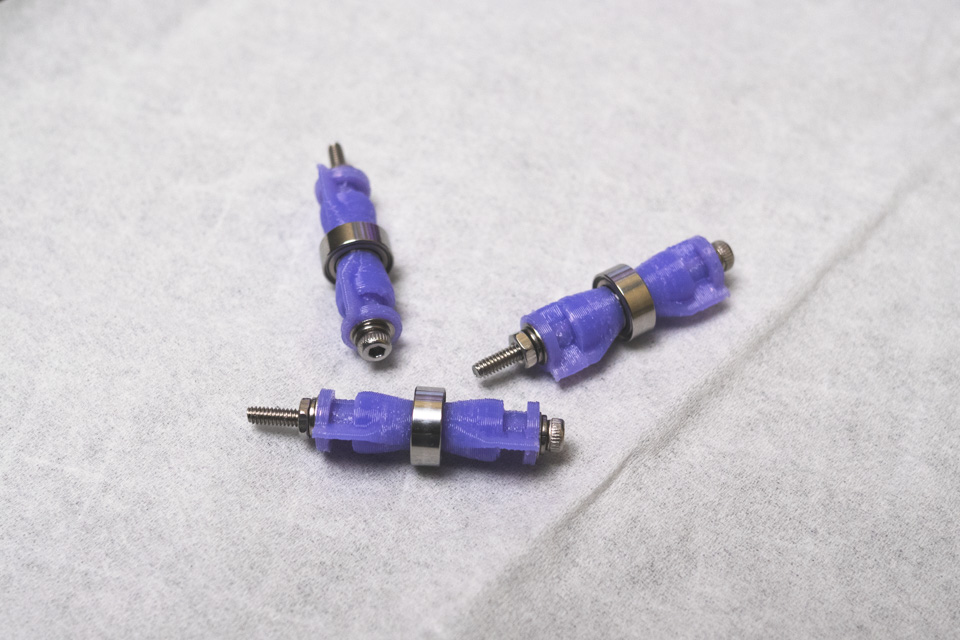
Like a glove!
Alternative ball
On the last screen of the previous chapter, you can see that the ball bearings have scratches on them. This is because I tried some alternative balls. And the material I chose was not the right one choice for sure. But we will talk about it later.
Additional buttons
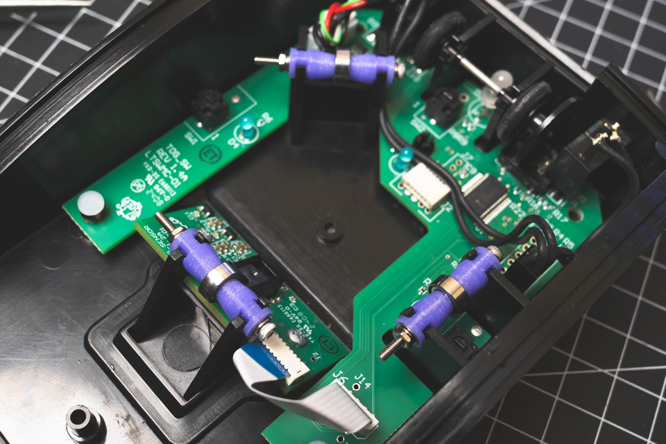
As I mentioned earlier, this device has the possibility to connect two additional custom buttons. For now, I just attached a module that I carved from wood and hardwired there two mechanical switches. Pretty raw, but does the job. A proper module is in progress.
Version: 2025_05_15_000003
Created by TennojiM
All rights reserved
© 2025
All rights reserved
© 2025